Quantum Computing
Circuit Examples
In this section we learn about how quantum circuits work and investigate some circuit identities. This is a large section and the reader is encouraged to use it as a guide for experimentation with quantum circuits.
Contents
- Quirk Quantum Simulator
- The CNOT Gate
- Creating Basic Superposition
- Entanglement
- The 'Upside-Down' CNOT
Quirk Quantum Simulator
It is important to experiment with quantum circuits to understand how they behave. To do this, you will need a quantum computing simulator. There are many good simulators with a range of strengths, but when beginning to learn about quantum circuits I strongly recommend using Quirk. Quirk runs in your browser and requires no installation, it is easy to use, offers instantaneous feedback and can handle up to 16 qubits.
To use Quirk, click and drag a gate onto the circuit. To remove the gate you can click it with the middle mouse button or drag it off the screen. We will use Quirk to demonstrate some circuit identities, I recommend trying the circuits out yourself along with me.
The CNOT Gate
(Getting Comfortable with Quirk)
We will start by looking at the CNOT gate. This is not an identity, but is a good introduction to using Quirk. First let’s drag a control onto the top qubit, and a target onto the bottom directly underneath it. We notice that our qubits started in the state |00⟩ and finish in the state |00⟩ (both qubits are OFF). We can see this on the amplitude display and the Bloch sphere displays:

Additionally, the measurement displays show we have 100% probability of measuring each qubit as OFF (You can hover your cursor over the displays to get more detailed information).
Now lets turn the top qubit ON before it hits the CNOT gate (i.e. input |01⟩). We see that both qubits finish in the state ON (|11⟩). This should not be a surprise since the CNOT gate switches the amplitudes |01⟩ and |11⟩. Note that our topmost qubit in Quirk is now our rightmost qubit in Dirac notation – you can choose which way round you write your qubits but remember to be consistent!

The final part of the exercise is to try the other possible input states (|10⟩ & |11⟩) and check that they produce the expected output.
Creating Basic Superposition
So far, we have not actually seen any quantum effects. Let’s add a H-gate to a qubit. Looking at the Bloch display, we see that the qubit is in the state |+⟩ as expected:

A huge advantage to simulators over real quantum computers is that we can ‘peak’ at the states of our qubits without destroying them. Lets now create the state |-⟩ by adding a Z-gate after the H-gate. We see our qubit state has the same magnitudes of |0⟩ and |1⟩, but it’s phase has changed. If we were to measure |+⟩ and |-⟩ states on a real quantum computer over many runs, we would get the same results (half ON and half OFF on average), but using a simulator we can see much more information. This is extremely useful for experimenting with and debugging circuits.

Entanglement
Lets create a Bell state as we saw in the previous section:

Notice our Bloch spheres have given up because our qubits are entangled and we can no longer describe their states independently. We can instead look at the amplitude display to see the state of the full system. As we saw in the last section, the states |00⟩ and |11⟩ have equal amplitudes of 1/√2 :
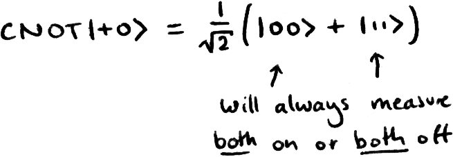
To get a better idea of what we’d see in a real quantum computer, let’s add a ‘chance’ probability display and drag it down to cover both lines. This display shows us the probability of measuring a combination of qubits. We can see that we have a 50% chance of measuring both OFF and both ON, but no chance of measuring one ON and one OFF (hover your cursor over the display to see the dialogue box):

I now recommend playing around with H, Z and CNOT gates and observing the states different combinations give.
The 'Upside-Down' CNOT Gate
Note: ‘Upside-Down’ is clunky terminology, but I wanted to avoid ‘reverse’ or ‘inverted’ since I normally use this to mean a circuit that reverses or ‘undoes’ an operation.
A popular quantum circuit identity is shown below. Recreate this circuit in Quirk and experiment with different input states:
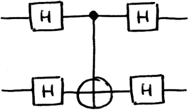
After trying each input state, you might come to the conclusion that this circuit is equivalent to a CNOT acting on the qubits ‘backwards’:

Verification
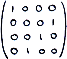
We can check this by doing matrix multiplications to prove the identity. The CNOT as we know has the matrix:

And switches the amplitude of the states |10⟩ and |11⟩. Our upside-down CNOT instead switches the amplitudes of the states |01⟩ and |11⟩, and therefore is described by the matrix:
To calculate the matrix of the two H-gates, we must use the Kronecker product as we did to describe the states of two qubits:


So the total matrix of this circuit is:
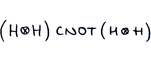


This is what your quantum simulator is doing behind the scenes, and it’s easy to see how adding more qubits can quickly result in large matrices with an extremely large number of elements. By using a matrix multiplication calculator or just taking my word for it, (I don’t recommend doing this by hand), we find that this calculation does give the expected matrix of the upside-down CNOT.
But Why?
Checking circuit identities in this way is a useful skill, but crunching numbers doesn’t always give us an understanding of what’s going on. To do so, let’s first look at this example:
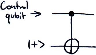
Here our target is in the state |+⟩. Applying an X-gate to a |+⟩ qubit has no effect, so it should be no surprise that the state of the control qubit has no effect on the state of the target qubit. Whether the controlled-X is applied or not, our target will remain in the state |+⟩. Experiment with different inputs on the control qubit and verify this.
Since we transform the state |0⟩ to the state |+⟩ and back using a H-gate, the following circuit will always output the target in the state |0⟩ regardless of what state the control is in:
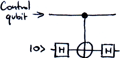
What if instead we were to pass the target as a |-⟩ qubit? We remember that:

So applying the X-gate introduces a negative phase. Interestingly, this negative phase not only applies to the target qubit, but also to the control qubit since their states are entangled. If our control qubit is in the state |0⟩, it will not introduce the negative phase, and pass through unchanged, but if our control qubit is in the state |1⟩, it will acquire the negative phase and come out of the circuit as -|1⟩:

This transformation has the effect of switching a |+⟩ state into a |-⟩ state:


We can see that the state of the target qubit switches the state of the control qubit. If you are lucky, it will now be clear how the upside-down CNOT circuit identity has the effect it does. If you are like the rest of us, you will need to revisit this example, experiment with it in Quirk and read other explanations (such as this concise breakdown from u/QCI-Austin).